Dendritic arm spacing in Copper Lead alloy
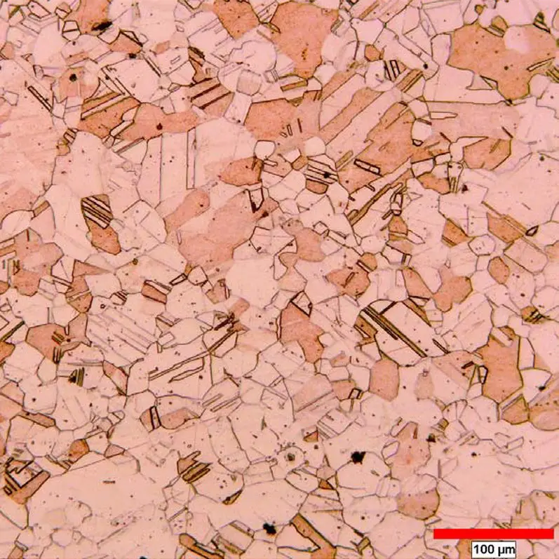
One tiff format image of dendritic copper lead alloy at 100X is submitted for dendrite arm spacing measurement.
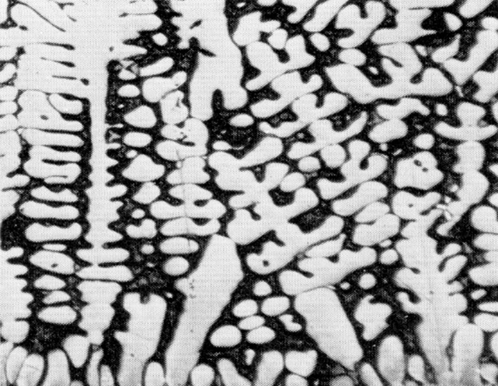
Figure 1. Original submitted image at 100X.
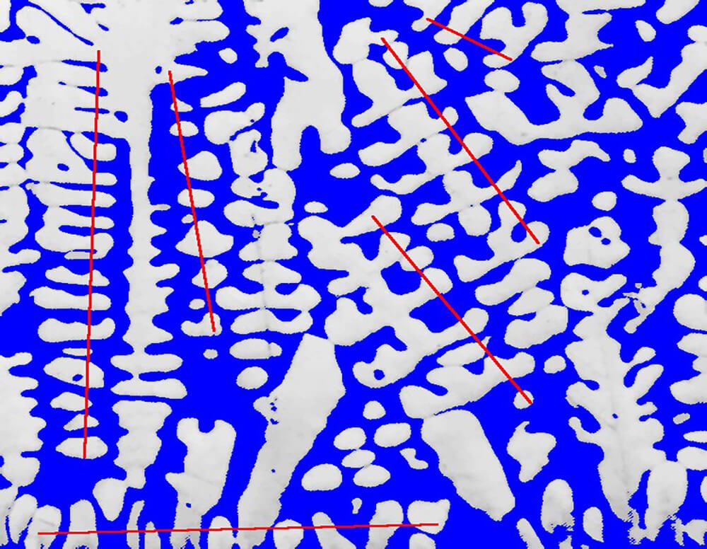
Figure 2. The lead matrix is binarized into blue bitplane. The user can draw some straight lines through dendrite arms to be measured.
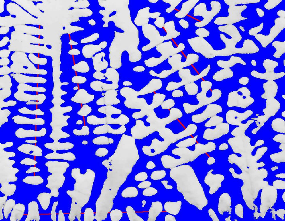
Figure 3. Binary operations are applied to keep only the part of the lines that cross the lead matrix (blue).
PURPOSE
Demonstrate the ability of the Clemex Vision image analysis system can measure average dendrite arm spacing. The methods and operations used are discussed in the report linked at the bottom of this page (click the Download PDF link below).

RESULTS
A well polished surface is essential to minimize the influence of scratches when identifying the cell intervals. Analyzing multiple fields could give more representative results. Final results can be printed directly from Clemex Vision. Raw data are linked to their respective objects for validation purpose. Raw data can also be exported in Excel format.